
March has been productive. We left off last time with a major decision to change out a key component, the microcontroller that handles all of our sensor IO and power management. We’ve had our heads down for the last couple of weeks working on that and a few other things.
tl;dr: New mainboard prototypes have been ordered, and should arrive in the next 2-4 weeks.
Electronics
The mainboard has been substantially updated to replace the IO microcontroller, make a few circuit tweaks, and alter the PCB form factor to fit the updated mechanicals that John has been working on. We’ve ordered 10 fully assembled prototypes from a candidate manufacturer which should arrive in the next 2-4 weeks.
The IO microcontroller handles the internal sensors, external sensor ports, and battery power management. We mentioned last update that this change was mostly driven by manufacturing concerns, and we’ll explore that decision process as part of a bigger topic in the future. The new chip is an STM32 (as opposed to an EFM32 from Silabs). They are more or less equivalent in terms of capability, though in general I will say I prefer the STM32 from a developer point of view—the tooling and documentation is better. The new part is also in a slightly more convenient form factor (and has more variety available should we need to change sizes). In general, it is slightly easier to work with all around.
Since we are changing out something so fundamental as one of the microcontrollers, it means we are scrapping the dozen or so prototypes we’ve already built (it isn’t worth the effort to support a separate branch of firmware for a dozen boards we’ll never make again). However, they are far from wasted—we got quite a lot of testing done on them. I’ve been able to do a lot of fine tuning which is incorporated in the next round of prototypes:
Sensor tuning
I’ve been working with the internal sensors built into every Pickup.
The sound level sensor has been tested and verified. It works fine and I was able to remove some debug components we don’t need.
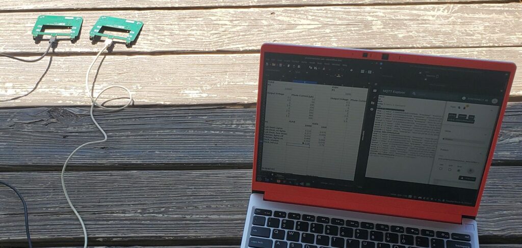
The light sensor has been tested across light levels ranging from total darkness to full sunlight. I found that the original circuit design couldn’t handle the full range; it would hit the maximum in outdoor shade, far lower than actual direct sun levels. I modified the circuit to add a two stage range selection, one is appropriate for indoor usage and the other for outdoor. My intention is that this will be transparent to the user. The firmware would automatically select whichever range is appropriate and you just get an overall light level reading.
The temperature sensor got a slight tweak to help with linearity, though it was already pretty decent so it was only a minor modification.
The accelerometer has been fine the whole time, though it does need some calibration to be accurate (which will be part of our manufacturing test program).
Power supplies
The mainboard has two on-board power supplies: one for USB power and one for battery power. I characterized both supplies over various load conditions and across 3 different prototypes to get some basic statistical data. All units track pretty closely together, and in general no major changes are needed.
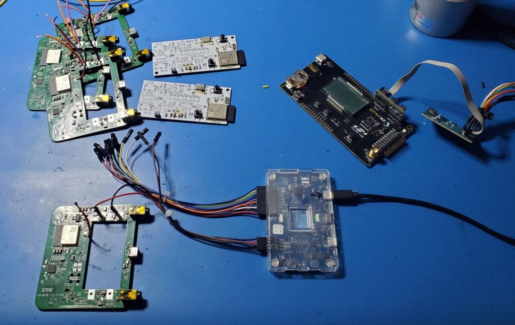
I did find and fix an issue doing lower power testing on the battery supply. In sleep mode the system should run a bit below 10 microamps, but I was measuring almost 40! Obviously a 4x increase in sleep mode current is a problem for battery life. This sort of thing can be difficult to track down: all electronic parts are “leaky” to some degree, sometimes in unexpected ways (which is why is so important to _test test test_). I ended up removing a ton of parts from one board to try and isolate the leak. It turned out to be a capacitor I added to the power supply input, originally a “just in case” part, but apparently it disturbed the power supply’s control loop in such a way that it used more power at idle. Removing that part solved the problem entirely.
Debug/test
Since we were making a breaking change, I figured I might as well take advantage of my last opportunity to fix a few issues to help with debug and manufacturing test. We have a custom connector that we use to load code to the two microcontrollers (and run tests on them), but I screwed up some of the connections on the original design. It worked but a few features were missing. I was able to clean this up and add a few things to help with the remaining firmware work.
Setbacks are often opportunities in disguise, and we got a lot of good opportunities out of this!
Mechanicals
John is very close to a final housing design that is both easier to build and will outperform our original design concept. We’ve been taking our time on this because we really cannot afford to get tooling for the plastics wrong. I ended up making a lot of PCB changes on the boards I just ordered to support the current mechanicals, and I think the extra work is going to pay off.
Stay tuned—the next update or two will feature the mechanicals more heavily.
Firmware
There hasn’t been much activity here lately, since I’ve been busy with the electronics changes. There’s some effort in switching out the lower layers of firmware to work on the new chip, but a lot of the core doesn’t change much. The new chip is one that I’m already familiar with from other work, so I’m not expecting any major surprises or issues here. Mostly I just need to get my hands on actual boards so I can connect all of the little bits back together.
What’s next
Now that we’re waiting for the new prototype boards to be built, focus will be on the sensor cartridges, firmware updates, cloud infrastructure, and finalizing the tooling for the plastics.
There’s a lot to do, but we are making forward progress every day. At some point over the next couple of updates, you’ll see us shifting towards showing off more of the actual functionality you’ll be using. We are very excited to start demonstrating real use cases.