Our manufacturing partners have been slow in getting back to us lately, which has made it hard to finalize production. Summer doldrums, I suppose. We’ve handed off the final files for circuitboards and plastic molds, and all we can do is keep poking them. It can be a headache keeping all the links in a supply chain connected, and when you’re the little guy, it’s harder still. I’m gathering the latest dates from our manufacturing partners, and should have a production and shipping schedule next update.
The process by which you manufacture a product at scale is itself a product, and that’s why it’s so much harder to make something for lots of people than it is to make one for yourself. (Never mind making it usable and supporting it.) Here’s Jeremy with more on that.
— John
Designing the test system
I’ve been working on the manufacturing test system in parallel with Pickup’s electronics and firmware. (If you’ve checked the forum, you’ve already read most of this.) The basic idea is that you insert a mainboard into a slot in the test system, plug in the cables, and then the system programs the board and checks all of the components and sensors to make sure they were soldered correctly and work.
This is the initial version—just enough to do functional test at the factory. We are planning a slightly fancier version that we will use in-house for final testing (so, every mainboard will actually go through two test systems before it ships). The in-house testing does extra things: measure power consumption of various components and operating modes, calibrate sensors, program shipping firmware, load security certificates, etc.
Here’s the 3D view of the board:
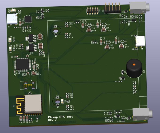
That black cylinder on the right side is a buzzer, to test the microphone. It’s probably going to be pretty annoying for the test operators (which in Austin will likely be me!), but it is necessary to actually test the mic.
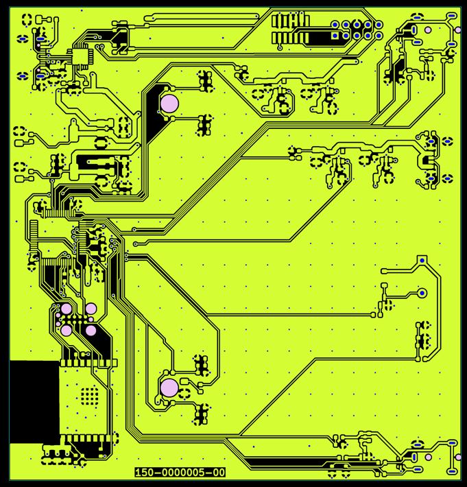
Here’s another view, of the top copper layer of the PCB. This is called a gerber. We have one for each layer of the board, and they are used to create the tooling to manufacture the PCB. We review the gerbers layer by layer to make sure the copper and other features are exactly the way we intend them. While most Pickup boards are 2 and 4 copper layers, my record is 14. You can probably guess it takes a while to review that many.
I’ve designed this system to go together in a hurry (took about a week). 99% of the components are from the Pickup mainboard—in fact, I actually started by copying the mainboard design over and then changing what I needed. This gives us a huge head start: all of the parts are already in our system and we already have working firmware projects for the two microcontrollers. I just need to modify the firmware to operate the test system, but the low level stuff already works.
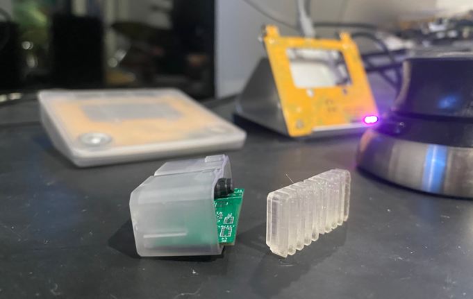
And here’s the produced MFG test board:
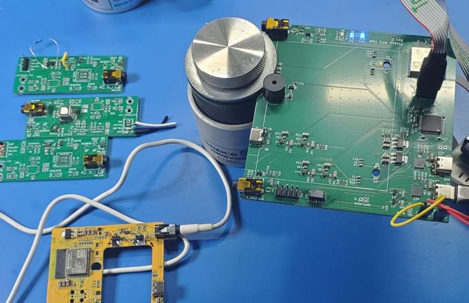
I can power it up and program it, and I’m in the process of writing the testing firmware.
On the left are three prototype peripheral boards, covering CO2, VOC, laser ranging, and spectral sensors. All four sensors are working and reporting data (when plugged in, of course!), though the spectral sensor needs a bit more work to convert the raw data into something that is more usable.
All of those sensors are miserable to hand mount on the board. They all have unique packages and requirements, tiny leads that are underneath the part, and tend to melt when heated, which is tricky because that is how soldering works. Some of those took me 1-2 hours to hand mount for a single chip (and on some of them I went through several chips before I got it right). Thankfully, the machines that do this at production have a much easier time of it.
Electronics
We’re working with our assembly partner to get the next round of mainboards built. This is going to be an exciting round because the next batch will be boards that will eventually be shipping to some of you.
Under the hood there has been a lot of firmware progress. Those peripheral boards are detected when plugged in and the appropriate drivers are loaded automatically. I’ve made various improvements to the MQTT infrastructure running on the ESP32, fixed memory leaks and regained some wasted space, improved robustness of a couple things, etc. There’s still a way to go, but the device functions pretty well already.
—Jeremy
Mechanicals
John here again. As I mentioned in the lede, things have been slow — frustrating when we’re this close to being done with this phase. I did hear back from the mold maker, and the good news is they didn’t have a problem molding my last-minute adjustments to shore up the battery clips. I believe I’ve addressed all their concerns in their moldability reports, adding draft here, thinning a wall there, etc. I’m just waiting for confirmation that they’re ready to start cutting the tool, and they’ll send plastic samples when it’s done.
In the meantime, I’ve moved on to designing packaging and shaping up the various sensor cartridges for production. Most of the cartridges share an injection molded main case, which gives us a reasonable economy of scale. But each needs a different fascia where the business end is poking out, and the best way to do that is with 3D printed parts. Better yet, I don’t have to wait on molders and mold makers to produce them.
Next update, in addition to schedule, I hope to have a lot more on software to show you.
Crossposted from Pickup Kickstarter update #9